Solar Street Light Installation Guide
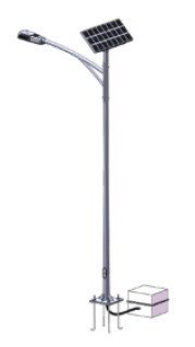
Solar street lights are a green and environmentally friendly lighting solution widely used in urban main roads, secondary roads, residential streets, parks, and squares. This guide aims to provide installers and engineers with detailed installation steps and precautions to ensure the efficient, stable, and safe operation of solar street lighting systems.
1. Preparatory Work
1.1 Foundation Materials
- Material Selection: Use reinforced concrete as the foundation material to ensure the stability of the lamp pole.
- Foundation Dimensions: The depth and width of the foundation should be designed according to the lamp pole height and wind resistance requirements of the photovoltaic components. Generally, the foundation depth should be greater than 1/6 of the lamp pole height, and the width should be greater than 1.5 times the depth.
- Calculation Formulas:
- Foundation Depth D = Hlamp height / 6
- Foundation Width W = 1.5 × D
1.2 Ground Bolts
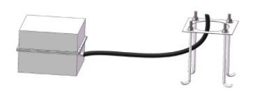
- Burial Depth: Ground bolts should be buried in the concrete at a depth greater than 20 times their diameter and securely welded to the main reinforcement.
- Rust Prevention: Ground bolts should be cleaned of rust, and the threaded parts should be protected.

1.3 Flange Bolts
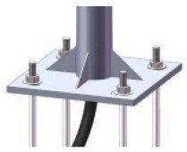
- Center Distribution: The central distribution diameter of the flange bolts should match the diameter of the lamp pole base flange holes.
- Fixing Method: Bolts should be secured with double nuts and spring washers to ensure a strong connection.
1.4 Grounding Protection
- Grounding Materials: Metal lamp poles, solar panel frames, brackets, and metal enclosures should have grounding protection.
- Grounding Body: The grounding body should be buried in the soil under the concrete foundation and welded securely with corrosion protection.
2. Lamp Pole Installation
2.1 Location Selection
- Well-Lit Area: Choose a location that has ample sunlight and no obstructions, ensuring the solar panel’s light-facing side remains shadow-free throughout the day.
- Temperature Range: Ensure that the ambient temperature used is between -20°C to 60°C. In colder environments, increase battery capacity as needed.

2.2 Lamp Pole Height
- Main Roads: Lamp pole height is typically 10-12 meters.
- Secondary Roads: Lamp pole height is typically 8-10 meters.
- Residential Streets: Lamp pole height is typically 5-8 meters.
- Parks/Squares: Lamp pole height is typically 3-5 meters.
2.3 Lamp Pole Fixing
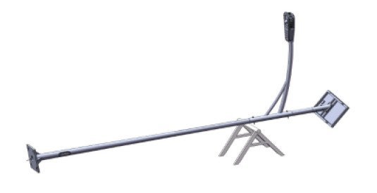
- Fixing Method: Secure the lamp pole to the foundation using ground bolts and flange bolts to ensure stability.
- Vertical Installation: Ensure the lamp pole is installed vertically, with a deviation of no more than 1%.

3. Solar Panel Installation
3.1 Orientation Angle
- Direction: The solar panels should face due south (in the Northern Hemisphere) to ensure they remain shadow-free throughout the day.
- Optimal Tilt Angle: Determine the optimal tilt angle based on local geographical and climatic conditions, e.g., the optimal tilt angle in Nanjing, Jiangsu, is 37°.
- Calculation Formula: The optimal tilt angle θ = Latitude + (10.5 – 11.3 × cos(Month))
3.2 Fixing Method
- Vibration Resistance: Use vibration-resistant screws to secure solar panels, ensuring stability in adverse weather conditions.
- Installation Location: Panels can be installed at the top of the lamppost or other suitable positions like rooftops, ensuring they have sufficient sunlight exposure without obstruction.
4. Battery Installation
4.1 Installation Position
- Ground Installation: Choose a well-ventilated and dry area to ensure battery cooling and safety.
- Waterproof Measures: Ensure the waterproof box has excellent waterproof performance to prevent rainwater ingress. It should be locked or have other anti-theft measures to prevent battery theft.
4.2 Connection
- Terminal Handling: Connect the battery terminals via proper wiring, ensuring correct positive and negative connections.
- Insulation Protection: Insulate the output terminals properly to prevent short circuits which can lead to significant accidents.
4.3 Temperature Management
- High-Temperature Resistance: Choose battery types that can withstand high temperatures, ensuring good ventilation to prevent overheating.
- Calculation Formula: Battery capacity C = (Pload × Tdischarge time) / (Vsystem voltage × Ddischarge depth)
- Where:
- C: Battery capacity (Ah)
- Pload: Load power (W)
- Tdischarge time: Discharge time (hours)
- Vsystem voltage: System voltage (V)
- Ddischarge depth: Discharge depth (typically 0.5)
- Where:
5. Controller Installation
5.1 Location Selection
- Avoid Sunlight and Rain: The controller should be installed at the top of the lamp pole or inside a waterproof box to avoid exposure to sunlight and rain.
- Wiring Sequence: Connect the wires in the following order: first connect the battery, then the solar panels, and finally the load, ensuring correct polarity.
5.2 Parameter Setting
- Light Control and Time Control: The controller should possess both light and time control capabilities, adjusting timing according to design requirements.
- Temperature Compensation Formula: Temperature compensation formula for the controller is as follows:
Vcompensated = Vreference + ΔT × Ktemperature compensation- Where:
- Vcompensated: Compensated voltage (V)
- Vreference: Reference voltage (V)
- ΔT: Temperature change (°C)
- Ktemperature compensation: Temperature compensation coefficient (-18 mV/°C)
- Where:
5.3 Automatic Protection
- Overload Protection: The sampling discharge current data should compare to the protection threshold. If it exceeds the threshold, the load should be shut off, with regular self-checks until the load returns to normal or repairs are completed.
- Over-Discharge Protection: Regular sampling of battery voltage should take place. If the battery voltage drops below the over-discharge point, disconnect the load to effectively protect battery lifespan.
- Overcharge Protection: During charging, set parameters for overcharge voltage and under-voltage protection to prevent battery overcharging.
6. Luminaire Installation

6.1 Luminaires Height
- Main Roads: Lamp pole height should be 10-12 meters, with a lamp tilt angle of 30°.
- Secondary Roads: Lamp pole height should be 8-10 meters, with a lamp tilt angle of 25°.
- Residential Streets: Lamp pole height should be 5-8 meters, with a lamp tilt angle of 20°.
- Parks/Squares: Lamp pole height should be 3-5 meters, with a lamp tilt angle of 15°.
6.2 Luminaire Adjustment
- Adjustable Mechanism: Add an adjustable clasp under the solar panel that allows for vertical adjustments of 10° to 60° and a full 360° rotation horizontally. The PLC controller can flexibly adjust the solar panel direction and angle to maintain optimal sunlight absorption.
- Testing Before Hoisting: Before hoisting the lamp, test the luminaire again with the battery to ensure it lights up, avoiding additional repair costs later.
7. System Commissioning
7.1 Initial Testing
- System Check: After installation, perform a comprehensive system check to ensure all components are connected correctly, with no short circuits or leakage.
- Function Testing: Test the light control and time control functions to confirm the luminaires turn on automatically at night and off during the day.
7.2 Parameter Verification
- Light Control + Time Control: It is recommended to use a combination of light and time control for discharging. If light intensity falls below 10 lux, delay 30 seconds before automatically starting the LED street light.
- Discharge Management: Calculate discharge watt-hours. For example:
- Total Discharge Watt-Hours: Total = 240 × 30 + 300 × 15 + 60 × 30 = 2250 Wh
- Discharge Amp-Hours: Discharge Ah = 2250 Wh / 12 V = 187.5 Ah
7.3 Brightness Adjustment
- Light Sensor: Use light sensors to collect external light intensity parameters to test the adaptive lighting function, adjusting the luminaire brightness over 30 minutes from 0 to the set brightness.
8. Maintenance and Care
8.1 Regular Inspections
- System Checks: Regularly check the operating status of solar panels, controllers, batteries, and luminaires to ensure normal system functionality.
- Cleaning Maintenance: Regularly clean the surface of solar panels to maintain light absorption efficiency.
- Fault Troubleshooting: Address any faults promptly to avoid affecting lighting performance and system longevity.
8.2 Cable Selection
- Cable Section: Select appropriate cables based on actual needs, ensuring the cable section and length meet the system’s voltage and current requirements.
- Calculation Formula: Cable section S = (2 × L × Icurrent × ΔUallowable voltage drop) / (ρ × Vsystem voltage)
- Where:
- S: Cable section (mm²)
- L: Cable length (m)
- Icurrent: Long-term working current in the circuit (A)
- ΔUallowable voltage drop: Allowable voltage drop in the circuit (V)
- ρ: Resistance coefficient (Copper: ρ = 0.0184 Ω·mm²/m, Aluminum: ρ = 0.031 Ω·mm²/m)
- Vsystem voltage: System voltage (V)
- Cable Section: Select appropriate cables based on actual needs, ensuring the cable section and length meet the system’s voltage and current requirements.
9. Special Situations Handling
9.1 Tree Shade Issues
- Urban Areas: In streets with street trees, avoid excessive pruning of branches due to solar panel installations. Consider installing panels on buildings, transmitting electricity through wires to the lamp position.
- Rural Areas: For new streets, consider greening needs to avoid planting street trees as a consequence of installing solar light systems.
9.2 AC and Solar Hybrid Street Lights
- AC Switching: The controller should have an AC switching function that automatically switches to mains power when solar power is insufficient. Ensure AC wiring connections are correct and safe.
- Testing AC Switching: During system testing, validate whether the AC switching function operates correctly, ensuring seamless transition to AC power when solar energy is inadequate.
10. Safety Considerations
10.1 Operational Standards
- Strict Compliance: Follow operational protocols rigorously during installation to ensure safety.
10.2 Electrical Safety
- Insulation Testing: Conduct insulation tests on all electrical equipment to ensure there are no leakage issues.
- Short Circuit Protection: Avoid short circuits during connections to ensure system safety.
10.3 Mechanical Safety
- Secure Fixation: Ensure that the lamp pole and solar panels are securely installed to prevent damage in adverse weather conditions.
- Vertical Alignment: Verify that the lamp pole is installed vertically, with a deviation not exceeding 1%.
10.4 Environmental Protection
- Avoid Pollution: Pay attention to environmental protection during the installation process to avoid causing pollution to the surrounding environment.
11. Common Issues and Solutions
11.1 Solar Panel Not Generating Power
- Check for Obstructions: Inspect if the panel is obstructed and clean the surface to ensure it is free of dust.
11.2 Luminaire Not Lighting
- Connection Check: Verify the connections between the controller, battery, and luminaire are correct and test each component for normal operation.
11.3 AC Switching Failure
- Wiring Inspection: Check the mains power wiring for correct connections to prevent disconnections or short circuits.
11.4 System Instability
- Installation Integrity Check: Check if all components are securely installed to prevent any looseness.
By following these steps and calculation formulas, installers and engineers can better comprehend and perform the installation of solar street lights, ensuring the efficient, stable, and safe operation of the system. We hope this guide assists you in your installation endeavors.